

Products
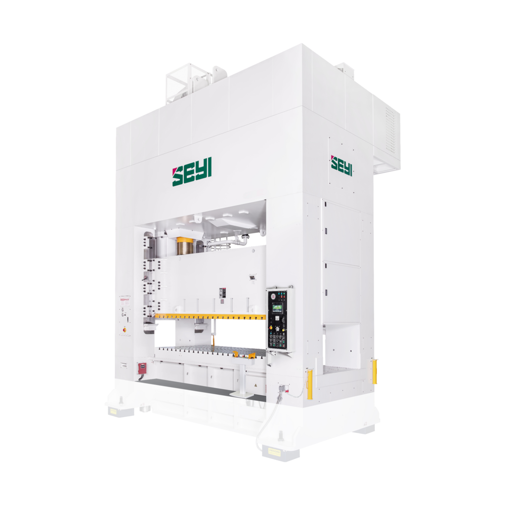
SLG Series|Straight Side Crank Link-Motion Press
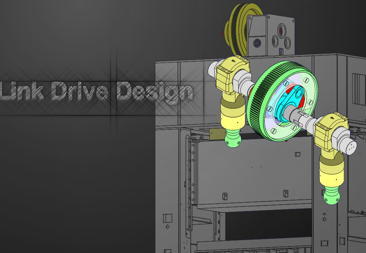
- Designed with tie-rod structure on the frame and adopting gear driving component with four connecting rods, the rigidity of main body increases extensively.The soft contact during press forming extensively reduces vibration, noise and heat, as well as extending die lifetime.
- The combination of pneumatic die cushion for big tonnage with tightening and adjusting component can address the needs for different stroke and action.
- With the use of high torque wet clutch/ brake, the lifetime of clutch increases and environmental protection is ensured.
- The highly respondent Hydraulic Overload Protector (HOLP) can effectively fix die stuck and prevent overloading.
- The human-machine interface can precisely control the stroke and pressure applied onto the die cushion. With PLC monitoring, the status of machine usage can be controlled at all times.
|
Model |
SLG2-300 |
SLG2-400 |
|||||||
|
Type |
S |
H |
S |
H |
|||||
|
Capacity |
kN |
3000 |
4000 |
||||||
|
Stroke Length |
mm |
300 |
200 |
400 |
250 |
||||
|
Strokes per Minute |
SPM |
15~30 |
25~50 |
15~26 |
25~50 |
||||
|
Tonnage Rating Point |
mm |
13 |
6.5 |
13 |
6.5 |
||||
|
Die Height |
mm |
600 |
700 |
||||||
|
Slide Adjustment |
mm |
200 |
250 |
||||||
|
Slide Area(LR×FB) |
1 |
mm |
2200×1200 |
2500×1400 |
|||||
|
2 |
2500×1200 |
2800×1400 |
|||||||
|
3 |
2800×1200 |
3100×1400 |
|||||||
|
4 |
3100×1200 |
3400×1400 |
|||||||
|
Bolster Area(LR×FB) |
1 |
mm |
2200×1370 |
2500×1400 |
|||||
|
2 |
2500×1370 |
2800×1400 |
|||||||
|
3 |
2800×1370 |
3100×1400 |
|||||||
|
4 |
3100×1370 |
3400×1400 |
|||||||
|
Bolster Thickness |
mm |
180 |
180 |
||||||
|
Window Opening |
Bolster Only |
FB × UD |
mm |
1000×500 |
1100×600 |
||||
|
Front to Back Rolling Bolster |
1000×500 |
1100×600 |
|||||||
|
Left to Right Rolling Bolster |
1670×700 |
1700×800 |
|||||||
|
Max. Upper Die Weight* |
Ton |
3 |
4 |
||||||
|
Required Air Pressure |
MPa |
0.6 |
0.6 |
||||||
|
Bolster Height |
Fixed Bolster |
mm |
850 |
850 |
|||||
|
Rolling Bolster |
660 |
660 |
|||||||
|
Main Motor |
w/o Die Cushion |
kW×P |
37×4 |
37×4 |
45×4 |
45×4 |
|||
|
w/ Die Cushion |
45×4 |
55×4 |
|||||||
|
Die Cushion |
Type** |
bellows |
cylinder |
||||||
|
Capacity |
kN |
550 |
— |
600 |
— |
||||
|
Stroke Length |
mm |
150 |
— |
200 |
— |
||||
|
Adjustment |
mm |
— |
— |
200 |
— |
||||
|
Cushion Pad Area(LR×FB) |
1 |
mm |
1700×900 |
— |
2000×900 |
— |
|||
|
2 |
2000×900 |
— |
2300×900 |
— |
|||||
|
3 |
2300×900 |
— |
2600×900 |
— |
|||||
|
4 |
2600×900 |
— |
2900×900 |
— |
|||||
|
|
SLG2-500 |
SLG2-600 |
||||||
|
Type |
S |
H |
S |
H |
||||
|
Capacity |
kN |
5000 |
6000 |
|||||
|
Stroke Length |
mm |
450 |
250 |
450 |
250 |
|||
|
Strokes per Minute |
SPM |
12~22 |
25~50 |
12~22 |
25~50 |
|||
|
Tonnage Rating Point |
mm |
13 |
6.5 |
13 |
6.5 |
|||
|
Die Height |
mm |
700 |
700 |
|||||
|
Slide Adjustment |
mm |
250 |
250 |
|||||
|
Slide Area(LR×FB) |
1 |
mm |
2500×1450 |
2500×1550 |
||||
|
2 |
2800×1450 |
2800×1550 |
||||||
|
3 |
3100×1450 |
3100×1550 |
||||||
|
4 |
3400×1450 |
3400×1550 |
||||||
|
Bolster Area(LR×FB) |
1 |
mm |
2500×1450 |
2500×1550 |
||||
|
2 |
2800×1450 |
2800×1550 |
||||||
|
3 |
3100×1450 |
3100×1550 |
||||||
|
4 |
3400×1450 |
3400×1550 |
||||||
|
Bolster Thickness |
mm |
180 |
250 |
|||||
|
Window Opening |
Bolster Only |
FB × UD |
mm |
1200×600 |
1300×600 |
|||
|
Front to Back Rolling Bolster |
1200×600 |
1300×600 |
||||||
|
Left to Right Rolling Bolster |
1750×800 |
1850×800 |
||||||
|
Max. Upper Die Weight* |
Ton |
4.5 |
5 |
|||||
|
Required Air Pressure |
MPa |
0.6 |
0.6 |
|||||
|
Bolster Height |
Fixed Bolster |
mm |
850 |
850 |
||||
|
Rolling Bolster |
660 |
660 |
||||||
|
Main Motor |
w/o Die Cushion |
kW×P |
55×4 |
55×4 |
55×4 |
|||
|
w/ Die Cushion |
75×4 |
|||||||
|
Die Cushion |
Type** |
cylinder |
cylinder |
|||||
|
Capacity |
kN |
800 |
— |
1000 |
— |
|||
|
Stroke Length |
mm |
220 |
— |
220 |
— |
|||
|
Adjustment |
mm |
220 |
— |
220 |
— |
|||
|
Cushion Pad Area(LR×FB) |
1 |
mm |
2000×950 |
— |
2000×950 |
— |
||
|
2 |
2300×950 |
— |
2300×950 |
— |
||||
|
3 |
2600×950 |
— |
2600×950 |
— |
||||
|
4 |
2900×950 |
— |
2900×950 |
— |
||||
|
Model |
SLG2-800 |
SLG2-1000 |
|||||||
|
Type |
S |
H |
S |
H |
|||||
|
Capacity |
kN |
8000 |
10000 |
||||||
|
Stroke Length |
mm |
450 |
300 |
450 |
300 |
||||
|
Strokes per Minute |
SPM |
10~20 |
20~40 |
10~20 |
20~40 |
||||
|
Tonnage Rating Point |
mm |
13 |
6.5 |
13 |
6.5 |
||||
|
Die Height |
mm |
800 |
800 |
||||||
|
Slide Adjustment |
mm |
300 |
300 |
||||||
|
Slide Area(LR×FB) |
1 |
mm |
2800×1550 |
3100×1550 |
|||||
|
2 |
3100×1550 |
3400×1550 |
|||||||
|
3 |
3400×1550 |
3700×1550 |
|||||||
|
4 |
3700×1550 |
4000×1550 |
|||||||
|
Bolster Area(LR×FB) |
1 |
mm |
2800×1550 |
3100×1550 |
|||||
|
2 |
3100×1550 |
3400×1550 |
|||||||
|
3 |
3400×1550 |
3700×1550 |
|||||||
|
4 |
3700×1550 |
4000×1550 |
|||||||
|
Bolster Thickness |
mm |
250 |
250 |
||||||
|
Window Opening |
Bolster Only |
FB × UD |
mm |
1500×700 |
1500×700 |
||||
|
Front to Back Rolling Bolster |
1500×700 |
1500×700 |
|||||||
|
Left to Right Rolling Bolster |
1850×900 |
1850×900 |
|||||||
|
Max. Upper Die Weight* |
Ton |
5.5 |
6 |
||||||
|
Required Air Pressure |
MPa |
0.6 |
0.6 |
||||||
|
Bolster Height |
Fixed Bolster |
mm |
850 |
850 |
|||||
|
Rolling Bolster |
660 |
740 |
|||||||
|
Main Motor |
w/o Die Cushion |
kW×P |
75×4 |
75×4 |
90×4 |
90×4 |
|||
|
w/ Die Cushion |
90×4 |
110×4 |
|||||||
|
Die Cushion |
Type** |
cylinder |
cylinder |
||||||
|
Capacity |
kN |
1200*** |
— |
1500 |
— |
||||
|
Stroke Length |
mm |
220 |
— |
220 |
— |
||||
|
Adjustment |
mm |
220 |
— |
220 |
— |
||||
|
Cushion Pad Area(LR×FB) |
1 |
mm |
2300×1300 |
— |
2600×1300 |
— |
|||
|
2 |
2600×1300 |
— |
2900×1300 |
— |
|||||
|
3 |
2900×1300 |
— |
3200×1300 |
— |
|||||
|
4 |
3200×1300 |
— |
3500×1300 |
— |
|||||
|
|
SLG2-1200 |
SLG2-1600 |
|||||||
|
Type |
S |
H |
S |
H |
|||||
|
Capacity |
kN |
12000 |
16000 |
||||||
|
Stroke Length |
mm |
450 |
300 |
450 |
300 |
||||
|
Strokes per Minute |
SPM |
10~20 |
20~40 |
10~20 |
20~40 |
||||
|
Tonnage Rating Point |
mm |
13 |
6.5 |
13 |
6.5 |
||||
|
Die Height |
mm |
800 |
800 |
||||||
|
Slide Adjustment |
mm |
300 |
300 |
||||||
|
Slide Area(LR×FB) |
1 |
mm |
3400×1550 |
3700×1800 |
|||||
|
2 |
3700×1550 |
4000×1800 |
|||||||
|
3 |
4000×1550 |
4300×1800 |
|||||||
|
4 |
4300×1550 |
4600×1800 |
|||||||
|
Bolster Area(LR×FB) |
1 |
mm |
3400×1550 |
3700×1800 |
|||||
|
2 |
3700×1550 |
4000×1800 |
|||||||
|
3 |
4000×1550 |
4300×1800 |
|||||||
|
4 |
4300×1550 |
4600×1800 |
|||||||
|
Bolster Thickness |
mm |
300 |
300 |
||||||
|
Window Opening |
Bolster Only |
FB × UD |
mm |
1500×700 |
1800×700 |
||||
|
Front to Back Rolling Bolster |
1500×700 |
1800×700 |
|||||||
|
Left to Right Rolling Bolster |
1850×900 |
2200×900 |
|||||||
|
Max. Upper Die Weight* |
Ton |
7 |
9 |
||||||
|
Required Air Pressure |
MPa |
0.6 |
0.6 |
||||||
|
Bolster Height |
Fixed Bolster` |
mm |
850 |
850 |
|||||
|
Rolling Bolster |
740 |
740 |
|||||||
|
Main Motor |
w/o Die Cushion |
kW×P |
90×4 |
90×4 |
110×4 |
110×4 |
|||
|
w/ Die Cushion |
110×4 |
132×4 |
|||||||
|
Die Cushion |
Type** |
cylinder |
cylinder |
||||||
|
Capacity |
kN |
2000 |
— |
2400 |
— |
||||
|
Stroke Length |
mm |
220 |
— |
220 |
— |
||||
|
Adjustment |
mm |
220 |
— |
220 |
— |
||||
|
Cushion Pad Area(LR×FB) |
1 |
mm |
2900×1300 |
— |
— |
— |
|||
|
2 |
3200×1300 |
— |
3500×1500 |
3500×1500 |
|||||
|
3 |
3500×1300 |
— |
3800×1500 |
3800×1500 |
|||||
|
4 |
3800×1300 |
— |
4100×1500 |
4100×1500 |
|||||
|
Model |
SLG4-500 |
SLG4-600 |
||||||
|
Type |
S |
H |
S |
H |
||||
|
Capacity |
kN |
5000 |
6000 |
|||||
|
Stroke Length |
mm |
450 |
250 |
450 |
250 |
|||
|
Strokes per Minute |
SPM |
12~22 |
25~50 |
12~22 |
25~50 |
|||
|
Tonnage Rating Point |
mm |
13 |
6.5 |
13 |
6.5 |
|||
|
Die Height |
mm |
700 |
700 |
|||||
|
Slide Adjustment |
mm |
250 |
250 |
|||||
|
Slide Area(LR×FB) |
1 |
mm |
2500×2000 |
2500×2000 |
||||
|
2 |
2800×2000 |
2800×2000 |
||||||
|
3 |
3100×2000 |
3100×2000 |
||||||
|
4 |
3400×2000 |
3400×2000 |
||||||
|
Bolster Area(LR×FB) |
1 |
mm |
2500×2000 |
2500×2000 |
||||
|
2 |
2800×2000 |
2800×2000 |
||||||
|
3 |
3100×2000 |
3100×2000 |
||||||
|
4 |
3400×2000 |
3400×2000 |
||||||
|
Bolster Thickness |
mm |
180 |
250 |
|||||
|
Window Opening |
Bolster Only |
FB × UD |
mm |
1800×600 |
1800×600 |
|||
|
Front to Back Rolling Bolster |
1800×600 |
1800×600 |
||||||
|
Left to Right Rolling Bolster |
2300×800 |
2300×800 |
||||||
|
Max. Upper Die Weight* |
Ton |
7 |
8 |
|||||
|
Required Air Pressure |
MPa |
0.6 |
0.6 |
|||||
|
Bolster Height |
Fixed Bolster |
mm |
660 |
660 |
||||
|
Rolling Bolster |
||||||||
|
Main Motor |
w/o Die Cushion |
kW×P |
55×4 |
55×4 |
55×4 |
|||
|
w/ Die Cushion |
75×4 |
|||||||
|
Die Cushion |
Type** |
cylinder |
cylinder |
|||||
|
Capacity |
kN |
800 |
1000 |
— |
||||
|
Stroke Length |
mm |
220 |
220 |
— |
||||
|
Adjustment |
mm |
220 |
220 |
— |
||||
|
Cushion Pad Area(LR×FB) |
1 |
mm |
2000×1300 |
— |
2000×1300 |
— |
||
|
2 |
2300×1300 |
— |
2300×1300 |
— |
||||
|
3 |
2600×1300 |
— |
2600×1300 |
— |
||||
|
4 |
2900×1300 |
— |
2900×1300 |
— |
||||
|
|
SLG4-800 |
SLG4-1000 |
SLG4-1200 |
|||||||||
|
Type |
S |
H |
S |
H |
S |
H |
||||||
|
Capacity |
kN |
8000 |
10000 |
12000 |
||||||||
|
Stroke Length |
mm |
450 |
300 |
450 |
300 |
450 |
300 |
|||||
|
Strokes per Minute |
SPM |
10~20 |
20~40 |
10~20 |
20~40 |
10~20 |
20~40 |
|||||
|
Tonnage Rating Point |
mm |
13 |
6.5 |
13 |
6.5 |
13 |
6.5 |
|||||
|
Die Height |
mm |
800 |
800 |
800 |
||||||||
|
Slide Adjustment |
mm |
300 |
300 |
300 |
||||||||
|
Slide Area(LR×FB) |
1 |
mm |
2800×2200 |
3100×2200 |
3400×2200 |
|||||||
|
2 |
3100×2200 |
3400×2200 |
3700×2200 |
|||||||||
|
3 |
3400×2200 |
3700×2200 |
4000×2200 |
|||||||||
|
4 |
3700×2200 |
4000×2200 |
4300×2200 |
|||||||||
|
Bolster Area(LR×FB) |
1 |
mm |
2800×2200 |
3100×2200 |
3400×2200 |
|||||||
|
2 |
3100×2200 |
3400×2200 |
3700×2200 |
|||||||||
|
3 |
3400×2200 |
3700×2200 |
4000×2200 |
|||||||||
|
4 |
3700×2200 |
4000×2200 |
4300×2200 |
|||||||||
|
Bolster Thickness |
mm |
250 |
250 |
300 |
||||||||
|
Window Opening |
Bolster Only |
FB × UD |
mm |
2000×700 |
2000×700 |
2000×700 |
||||||
|
Front to Back Rolling Bolster |
2000×700 |
2000×700 |
2000×700 |
|||||||||
|
Left to Right Rolling Bolster |
2500×900 |
2500×900 |
2500×900 |
|||||||||
|
Max. Upper Die Weight* |
Ton |
9 |
9 |
10 |
||||||||
|
Required Air Pressure |
MPa |
0.6 |
0.6 |
0.6 |
||||||||
|
Bolster Height |
Fixed Bolster |
mm |
660 |
740 |
740 |
|||||||
|
Rolling Bolster |
||||||||||||
|
Main Motor |
w/o Die Cushion |
kW×P |
75×4 |
75×4 |
90×4 |
90×4 |
90×4 |
90×4 |
||||
|
w/ Die Cushion |
90×4 |
110×4 |
110×4 |
|||||||||
|
Die Cushion |
Type** |
cylinder |
cylinder |
cylinder |
||||||||
|
Capacity |
kN |
1200* |
— |
1500 |
— |
2000 |
— |
|||||
|
Stroke Length |
mm |
220 |
— |
220 |
— |
220 |
— |
|||||
|
Adjustment |
mm |
220 |
— |
220 |
— |
220 |
— |
|||||
|
Cushion Pad Area(LR×FB) |
1 |
mm |
2300×1500 |
— |
2600×1500 |
— |
2900×1500 |
— |
||||
|
2 |
2600×1500 |
— |
2900×1500 |
— |
3200×1500 |
— |
||||||
|
3 |
2900×1500 |
— |
3200×1500 |
— |
3500×1500 |
— |
||||||
|
4 |
3200×1500 |
— |
3500×1500 |
— |
3800×1500 |
— |
||||||
* Upper die weight may vary in table size. Please contact your sales representative for more information.
** For selecting 1200kN, 1500kN and 2000kN air cylinder die cushions, bolster area in FB should be at least 1700mm.
*** For selecting 2400kN, 3000kN air cylinder die cushions, bolster area in FB should be at least 1900mm.
**** For SLG2-800-1, only 1000kN die cushion is available.
* For SLG4-800-1, only 1000kN die cushion is available.
※ Slide and bolster area up to 5500x1550 by request.
※ This specification is subject to change without
notice.
|
Model |
SLG2-330 |
SLG2-440 |
|||||||
|
Type |
S |
H |
S |
H |
|||||
|
Capacity |
U.S. Ton |
330 |
440 |
||||||
|
Stroke Length |
in |
11.81 |
7.87 |
15.75 |
9.84 |
||||
|
Strokes per Minute |
SPM |
15~30 |
25~50 |
15~26 |
25~50 |
||||
|
Tonnage Rating Point |
in |
0.51 |
0.26 |
0.51 |
0.26 |
||||
|
Die Height |
in |
23.62 |
27.56 |
||||||
|
Slide Adjustment |
in |
7.87 |
9.84 |
||||||
|
Slide Area(LR×FB) |
1 |
in |
86.61×47.24 |
98.43×55.12 |
|||||
|
2 |
98.43×47.24 |
110.24×55.12 |
|||||||
|
3 |
110.24×47.24 |
122.05×55.12 |
|||||||
|
4 |
122.05×47.24 |
133.86×55.12 |
|||||||
|
Bolster Area(LR×FB) |
1 |
in |
86.61×53.94 |
98.43×55.12 |
|||||
|
2 |
98.43×53.94 |
110.24×55.12 |
|||||||
|
3 |
110.24×53.94 |
122.05×55.12 |
|||||||
|
4 |
122.05×53.94 |
133.86×55.12 |
|||||||
|
Bolster Thickness |
in |
7.09 |
7.09 |
||||||
|
Window Opening |
Bolster Only |
FB × UD |
in |
39.37×19.69 |
43.31×23.62 |
||||
|
Front to Back Rolling Bolster |
39.37×19.69 |
43.31×23.62 |
|||||||
|
Left to Right Rolling Bolster |
65.74×27.56 |
66.93×31.5 |
|||||||
|
Max. Upper Die Weight* |
LBS |
6600 |
8800 |
||||||
|
Required Air Pressure |
PSI |
85 |
85 |
||||||
|
Bolster Height |
Fixed Bolster |
in |
33.46 |
33.46 |
|||||
|
Rolling Bolster |
25.98 |
25.98 |
|||||||
|
Main Motor |
w/o Die Cushion |
HP×P |
50×4 |
50×4 |
60×4 |
60×4 |
|||
|
w/ Die Cushion |
60×4 |
75×4 |
|||||||
|
Die Cushion |
Type** |
bellows |
cylinder |
||||||
|
Capacity |
U.S. Ton |
60.5 |
66 |
||||||
|
Stroke Length |
in |
5.91 |
7.87 |
||||||
|
Adjustment |
in |
— |
7.87 |
||||||
|
Cushion Pad Area(LR×FB) |
1 |
in |
66.93×35.43 |
— |
78.74×35.43 |
— |
|||
|
2 |
78.74×35.43 |
— |
90.55×35.43 |
— |
|||||
|
3 |
90.55×35.43 |
— |
102.36×35.43 |
— |
|||||
|
4 |
102.36×35.43 |
— |
114.17×35.43 |
— |
|||||
|
|
SLG2-550 |
SLG2-660 |
||||||
|
Type |
S |
H |
S |
H |
||||
|
Capacity |
U.S. Ton |
550 |
660 |
|||||
|
Stroke Length |
in |
17.72 |
9.84 |
17.72 |
9.84 |
|||
|
Strokes per Minute |
SPM |
12~22 |
25~50 |
12~22 |
25~50 |
|||
|
Tonnage Rating Point |
in |
0.51 |
0.26 |
0.51 |
0.26 |
|||
|
Die Height |
in |
27.56 |
27.56 |
|||||
|
Slide Adjustment |
in |
9.84 |
9.84 |
|||||
|
Slide Area(LR×FB) |
1 |
in |
98.43×57.09 |
98.43×61.02 |
||||
|
2 |
110.24×57.09 |
110.24×61.02 |
||||||
|
3 |
122.05×57.09 |
122.05×61.02 |
||||||
|
4 |
133.86×57.09 |
133.86×61.02 |
||||||
|
Bolster Area(LR×FB) |
1 |
in |
98.43×57.09 |
98.43×61.02 |
||||
|
2 |
110.24×57.09 |
110.24×61.02 |
||||||
|
3 |
122.05×57.09 |
122.05×61.02 |
||||||
|
4 |
133.86×57.09 |
133.86×61.02 |
||||||
|
Bolster Thickness |
in |
7.09 |
9.84 |
|||||
|
Window Opening |
Bolster Only |
FB × UD |
in |
47.24×23.62 |
51.18×23.62 |
|||
|
Front to Back Rolling Bolster |
47.24×23.62 |
51.18×23.62 |
||||||
|
Left to Right Rolling Bolster |
68.9×31.5 |
72.83×31.5 |
||||||
|
Max. Upper Die Weight* |
LBS |
9900 |
11000 |
|||||
|
Required Air Pressure |
PSI |
85 |
85 |
|||||
|
Bolster Height |
Fixed Bolster |
in |
33.46 |
33.46 |
||||
|
Rolling Bolster |
25.98 |
25.98 |
||||||
|
Main Motor |
w/o Die Cushion |
HP×P |
75×4 |
75×4 |
75×4 |
|||
|
w/ Die Cushion |
100×4 |
|||||||
|
Die Cushion |
Type** |
cylinder |
cylinder |
|||||
|
Capacity |
U.S. Ton |
88 |
110 |
|||||
|
Stroke Length |
in |
8.66 |
8.66 |
|||||
|
Adjustment |
in |
8.66 |
8.66 |
|||||
|
Cushion Pad Area(LR×FB) |
1 |
in |
78.74×37.4 |
— |
78.74×37.4 |
— |
||
|
2 |
90.55×37.4 |
— |
90.55×37.4 |
— |
||||
|
3 |
102.36×37.4 |
— |
102.36×37.4 |
— |
||||
|
4 |
114.17×37.4 |
— |
114.17×37.4 |
— |
||||
|
Model |
SLG2-880 |
SLG2-1100 |
|||||||
|
Type |
S |
H |
S |
H |
|||||
|
Capacity |
U.S. Ton |
880 |
1100 |
||||||
|
Stroke Length |
in |
17.72 |
11.81 |
17.72 |
11.81 |
||||
|
Strokes per Minute |
SPM |
10~20 |
20~40 |
10~20 |
20~40 |
||||
|
Tonnage Rating Point |
in |
0.51 |
0.26 |
0.51 |
0.26 |
||||
|
Die Height |
in |
31.50 |
31.50 |
||||||
|
Slide Adjustment |
in |
11.81 |
11.81 |
||||||
|
Slide Area(LR×FB) |
1 |
in |
110.24×61.02 |
122.05×61.02 |
|||||
|
2 |
122.05×61.02 |
133.86×61.02 |
|||||||
|
3 |
133.86×61.02 |
145.67×61.02 |
|||||||
|
4 |
145.67×61.02 |
157.48×61.02 |
|||||||
|
Bolster Area(LR×FB) |
1 |
in |
110.24×61.02 |
122.05×61.02 |
|||||
|
2 |
122.05×61.02 |
133.86×61.02 |
|||||||
|
3 |
133.86×61.02 |
145.67×61.02 |
|||||||
|
4 |
145.67×61.02 |
157.48×61.02 |
|||||||
|
Bolster Thickness |
in |
9.84 |
9.84 |
||||||
|
Window Opening |
Bolster Only |
FB × UD |
in |
59.06×27.56 |
59.06×27.56 |
||||
|
Front to Back Rolling Bolster |
59.06×27.56 |
59.06×27.56 |
|||||||
|
Left to Right Rolling Bolster |
72.83×35.43 |
72.83×35.43 |
|||||||
|
Max. Upper Die Weight* |
LBS |
12100 |
13200 |
||||||
|
Required Air Pressure |
PSI |
85 |
85 |
||||||
|
Bolster Height |
Fixed Bolster |
in |
33.46 |
33.46 |
|||||
|
Rolling Bolster |
25.98 |
29.13 |
|||||||
|
Main Motor |
w/o Die Cushion |
HP×P |
100×4 |
100×4 |
125×4 |
125×4 |
|||
|
w/ Die Cushion |
125×4 |
150×4 |
|||||||
|
Die Cushion |
Type** |
cylinder |
cylinder |
||||||
|
Capacity |
U.S. Ton |
132(**) |
165 |
||||||
|
Stroke Length |
in |
8.66 |
8.66 |
||||||
|
Adjustment |
in |
8.66 |
8.66 |
||||||
|
Cushion Pad Area(LR×FB) |
1 |
in |
90.55×51.18 |
— |
102.36×51.18 |
— |
|||
|
2 |
102.36×51.18 |
— |
114.17×51.18 |
— |
|||||
|
3 |
114.17×51.18 |
— |
125.98×51.18 |
— |
|||||
|
4 |
125.98×51.18 |
— |
137.8×51.18 |
— |
|||||
|
|
SLG2-1320 |
SLG2-1760 |
|||||||
|
Type |
S |
H |
S |
H |
|||||
|
Capacity |
U.S. Ton |
1320 |
1760 |
||||||
|
Stroke Length |
in |
17.72 |
11.81 |
17.72 |
11.81 |
||||
|
Strokes per Minute |
SPM |
10~20 |
20~40 |
10~20 |
20~40 |
||||
|
Tonnage Rating Point |
in |
0.51 |
0.26 |
0.51 |
0.26 |
||||
|
Die Height |
in |
31.50 |
31.50 |
||||||
|
Slide Adjustment |
in |
11.81 |
11.81 |
||||||
|
Slide Area(LR×FB) |
1 |
in |
133.86×61.02 |
145.67×70.87 |
|||||
|
2 |
145.67×61.02 |
157.48×70.87 |
|||||||
|
3 |
157.48×61.02 |
169.29×70.87 |
|||||||
|
4 |
169.29×61.02 |
181.10×70.87 |
|||||||
|
Bolster Area(LR×FB) |
1 |
in |
133.86×61.02 |
145.67×70.87 |
|||||
|
2 |
145.67×61.02 |
157.48×70.87 |
|||||||
|
3 |
157.48×61.02 |
169.29×70.87 |
|||||||
|
4 |
169.29×61.02 |
181.10×70.87 |
|||||||
|
Bolster Thickness |
in |
11.81 |
11.81 |
||||||
|
Window Opening |
Bolster Only |
FB × UD |
in |
59.06×27.56 |
70.87×27.56 |
||||
|
Front to Back Rolling Bolster |
59.06×27.56 |
70.87×27.56 |
|||||||
|
Left to Right Rolling Bolster |
72.83×35.43 |
86.61×35.43 |
|||||||
|
Max. Upper Die Weight* |
LBS |
15400 |
19800 |
||||||
|
Required Air Pressure |
PSI |
85 |
85 |
||||||
|
Bolster Height |
Fixed Bolster |
in |
33.46 |
33.46 |
|||||
|
Rolling Bolster |
29.13 |
29.13 |
|||||||
|
Main Motor |
w/o Die Cushion |
HP×P |
125×4 |
125×4 |
150×4 |
150×4 |
|||
|
w/ Die Cushion |
150×4 |
175×4 |
|||||||
|
Die Cushion |
Type** |
cylinder |
cylinder |
||||||
|
Capacity |
U.S. Ton |
220 |
264 |
||||||
|
Stroke Length |
in |
8.66 |
8.66 |
||||||
|
Adjustment |
in |
8.66 |
8.66 |
||||||
|
Cushion Pad Area(LR×FB) |
1 |
in |
114.17×51.18 |
— |
— |
— |
|||
|
2 |
125.98×51.18 |
— |
137.80×59.06 |
— |
|||||
|
3 |
137.8×51.18 |
— |
149.61×59.06 |
— |
|||||
|
4 |
149.61×51.18 |
— |
161.42×59.06 |
— |
|||||
|
Model |
SLG4-550 |
SLG4-660 |
||||||
|
Type |
S |
H |
S |
H |
||||
|
Capacity |
U.S. Ton |
550 |
660 |
|||||
|
Stroke Length |
in |
17.72 |
9.84 |
17.72 |
9.84 |
|||
|
Strokes per Minute |
SPM |
12~22 |
25~50 |
12~22 |
25~50 |
|||
|
Tonnage Rating Point |
in |
0.51 |
0.26 |
0.51 |
0.26 |
|||
|
Die Height |
in |
27.56 |
27.56 |
|||||
|
Slide Adjustment |
in |
9.84 |
9.84 |
|||||
|
Slide Area(LR×FB) |
1 |
in |
98.43×78.74 |
98.43×78.74 |
||||
|
2 |
110.24×78.74 |
110.24×78.74 |
||||||
|
3 |
122.05×78.74 |
122.05×78.74 |
||||||
|
4 |
133.86×78.74 |
133.86×78.74 |
||||||
|
Bolster Area(LR×FB) |
1 |
in |
98.43×78.74 |
98.43×78.74 |
||||
|
2 |
110.24×78.74 |
110.24×78.74 |
||||||
|
3 |
122.05×78.74 |
122.05×78.74 |
||||||
|
4 |
133.86×78.74 |
133.86×78.74 |
||||||
|
Bolster Thickness |
in |
7.09 |
9.84 |
|||||
|
Window Opening |
Bolster Only |
FB × UD |
in |
70.87×23.62 |
70.87×23.62 |
|||
|
Front to Back Rolling Bolster |
70.87×23.62 |
70.87×23.62 |
||||||
|
Left to Right Rolling Bolster |
90.55×31.50 |
90.55×31.50 |
||||||
|
Max. Upper Die Weight* |
LBS |
15400 |
17600 |
|||||
|
Required Air Pressure |
PSI |
85 |
85 |
|||||
|
Bolster Height |
Fixed Bolster |
in |
25.98 |
25.98 |
||||
|
Rolling Bolster |
||||||||
|
Main Motor |
w/o Die Cushion |
HP×P |
75×4 |
75×4 |
75×4 |
|||
|
w/ Die Cushion |
100×4 |
|||||||
|
Die Cushion |
Type** |
cylinder |
cylinder |
|||||
|
Capacity |
U.S. Ton |
88 |
110 |
— |
||||
|
Stroke Length |
in |
8.66 |
8.66 |
— |
||||
|
Adjustment |
in |
8.66 |
8.66 |
— |
||||
|
Cushion Pad Area(LR×FB) |
1 |
in |
78.74×51.18 |
78.74×51.18 |
— |
|||
|
2 |
90.55×51.18 |
90.55×51.18 |
— |
|||||
|
3 |
102.36×51.18 |
102.36×51.18 |
— |
|||||
|
4 |
114.17×51.18 |
114.17×51.18 |
— |
|||||
|
|
SLG4-880 |
SLG4-1100 |
SLG4-1320 |
|||||||||
|
Type |
S |
S |
H |
S |
H |
H |
||||||
|
Capacity |
U.S. Ton |
880 |
1100 |
1320 |
||||||||
|
Stroke Length |
in |
17.72 |
11.81 |
17.72 |
11.81 |
17.72 |
11.81 |
|||||
|
Strokes per Minute |
SPM |
10~20 |
20~40 |
10~20 |
20~40 |
10~20 |
20~40 |
|||||
|
Tonnage Rating Point |
in |
0.51 |
0.26 |
0.51 |
0.26 |
0.51 |
0.26 |
|||||
|
Die Height |
in |
31.50 |
31.50 |
31.50 |
||||||||
|
Slide Adjustment |
in |
11.81 |
11.81 |
11.81 |
||||||||
|
Slide Area(LR×FB) |
1 |
in |
110.24×86.61 |
122.05×86.61 |
133.86×86.61 |
|||||||
|
2 |
122.05×86.61 |
133.86×86.61 |
145.67×86.61 |
|||||||||
|
3 |
133.86×86.61 |
145.67×86.61 |
157.48×86.61 |
|||||||||
|
4 |
145.67×86.61 |
157.48×86.61 |
169.29×86.61 |
|||||||||
|
Bolster Area(LR×FB) |
1 |
in |
110.24×86.61 |
122.05×86.61 |
133.86×86.61 |
|||||||
|
2 |
122.05×86.61 |
133.86×86.61 |
145.67×86.61 |
|||||||||
|
3 |
133.86×86.61 |
145.67×86.61 |
157.48×86.61 |
|||||||||
|
4 |
145.67×86.61 |
157.48×86.61 |
169.29×86.61 |
|||||||||
|
Bolster Thickness |
in |
9.84 |
9.84 |
11.81 |
||||||||
|
Window Opening |
Bolster Only |
FB × UD |
in |
78.74×27.56 |
78.74×27.56 |
78.74×27.56 |
||||||
|
Front to Back Rolling Bolster |
78.74×27.56 |
78.74×27.56 |
78.74×27.56 |
|||||||||
|
Left to Right Rolling Bolster |
98.43×35.43 |
98.43×35.43 |
98.43×35.43 |
|||||||||
|
Max. Upper Die Weight* |
LBS |
19800 |
19800 |
22000 |
||||||||
|
Required Air Pressure |
PSI |
85 |
85 |
85 |
||||||||
|
Bolster Height |
Fixed Bolster |
in |
25.98 |
29.13 |
29.13 |
|||||||
|
Rolling Bolster |
||||||||||||
|
Main Motor |
w/o Die Cushion |
HP×P |
100×4 |
100×4 |
125×4 |
125×4 |
125×4 |
125×4 |
||||
|
w/ Die Cushion |
125×4 |
150×4 |
150×4 |
|||||||||
|
Die Cushion |
Type** |
cylinder |
cylinder |
cylinder |
||||||||
|
Capacity |
U.S. Ton |
132(*) |
— |
165 |
— |
220 |
— |
|||||
|
Stroke Length |
in |
8.66 |
— |
8.66 |
— |
8.66 |
— |
|||||
|
Adjustment |
in |
8.66 |
— |
8.66 |
— |
8.66 |
— |
|||||
|
Cushion Pad Area(LR×FB) |
1 |
in |
90.55×59.06 |
— |
223.62×59.06 |
— |
114.17×59.06 |
— |
||||
|
2 |
102.36×59.06 |
— |
114.17×59.06 |
— |
125.98×59.06 |
— |
||||||
|
3 |
114.17×59.06 |
— |
125.98×59.06 |
— |
137.8×59.06 |
— |
||||||
|
4 |
125.98×59.06 |
— |
137.8×59.06 |
— |
149.61×59.06 |
— |
||||||
* Upper die weight may vary in table size. Please contact your sales representative for more information.
** For selecting 132T, 165T and 220T air cylinder die cushions, bolster area in FB should be at least 66.93in.
*** For selecting 264T, 330T air cylinder die cushions, bolster area in FB should be at least 74.80in.
**** For SLG2-880-1, only 110T die cushion is available.
* For SLG4-880-1, only 110T die cushion is available
※ Slide and bolster area up to 216.53x61.02in by request.
※ This specification is subject to change without
notice.
Introduction on Straight Side Crank Link-Motion Press (SLG series)
Straight Side Crank Link-Motion Press (SLG series) Auto parts