Products

SAG Series|Straight Side Crank Press
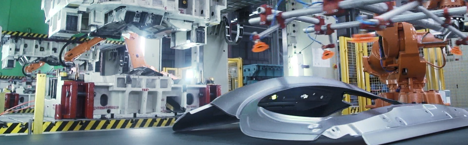
Its long history of power, precision, and reliability gives manufacturers the peace of mind knowing their plant can handle the toughest, grittiest jobs. Manufacturers looking to complete medium to large operations should look no further. The SAG series is engineered specifically for the most common, yet challenging operations today.
- The SAG is SEYI’s recommended mechanical press for medium to large operations using automatic feed, progressive die, and transfer systems.
- The tie rod frame offers excellent rigidity to resist deflection for better stamping.
- The design makes the integration and automation seamless. 99% of SAGs integrate with ancillary equipment.
- The SAG features wide-spaced connecting rods to provide stability with various types of dies, giving manufacturers great flexibility.
|
Model |
SAG2-300 |
SAG2-400 |
SAG2-500 |
||||||
|
Type |
S |
H |
S |
H |
S |
H |
|||
|
Capacity |
kN |
3000 |
4000 |
5000 |
|||||
|
Stroke Length |
mm |
300 |
200 |
400 |
250 |
450 |
250 |
||
|
Strokes per Minute |
SPM |
15~30 |
25~50 |
15~26 |
25~50 |
12~22 |
25~50 |
||
|
Tonnage Rating Point |
mm |
13 |
6.5 |
13 |
6.5 |
13 |
6.5 |
||
|
Die Height |
mm |
600 |
700 |
700 |
|||||
|
Slide Adjustment |
mm |
200 |
250 |
250 |
|||||
|
Slide Area(LR×FB) |
1 |
mm |
2200×1200 |
2500×1400 |
2500×1450 |
||||
|
2 |
2500×1200 |
2800×1400 |
2800×1450 |
||||||
|
3 |
2800×1200 |
3100×1400 |
3100×1450 |
||||||
|
4 |
3100×1200 |
3400×1400 |
3400×1450 |
||||||
|
5 |
3400×1200 |
3700×1400 |
3700×1450 |
||||||
|
Bolster Area(LR×FB) |
1 |
mm |
2200×1370 |
2500×1400 |
2500×1450 |
||||
|
2 |
2500×1370 |
2800×1400 |
2800×1450 |
||||||
|
3 |
2800×1370 |
3100×1400 |
3100×1450 |
||||||
|
4 |
3100×1370 |
3400×1400 |
3400×1450 |
||||||
|
5 |
3400×1370 |
3700×1400 |
3700×1450 |
||||||
|
Bolster Thickness |
mm |
180 |
180 |
180 |
|||||
|
Window Opening |
Bolster Only |
FB × UD |
mm |
1000×500 |
1100×600 |
1200×600 |
|||
|
Front to Back Rolling Bolster |
1000×500 |
1100×600 |
1200×600 |
||||||
|
Left to Right Rolling Bolster |
1670×700 |
1700×800 |
1750×800 |
||||||
|
Max. Upper Die Weight* |
Ton |
3 |
4 |
4.5 |
|||||
|
Required Air Pressure |
MPa |
0.55 |
0.55 |
0.55 |
|||||
|
Bolster Height |
Fixed Bolster |
mm |
850 |
850 |
850 |
||||
|
Rolling Bolster |
660 |
660 |
660 |
||||||
|
Main Motor |
w/o Die Cushion |
kW×P |
37×4 |
45×4 |
55×4 |
||||
|
w/ Die Cushion |
|||||||||
|
Die Cushion |
Type** |
bellows |
cylinder |
cylinder |
|||||
|
Capacity |
kN |
550 |
— |
600 |
— |
800 |
— |
||
|
Stroke Length |
mm |
150 |
— |
200 |
— |
220 |
— |
||
|
Adjustment |
mm |
— |
— |
200 |
— |
220 |
— |
||
|
Cushion Pad Area(LR×FB) |
1 |
mm |
1700×900 |
— |
2000×900 |
— |
2000×950 |
— |
|
|
2 |
2000×900 |
— |
2300×900 |
— |
2300×950 |
— |
|||
|
3 |
2300×900 |
— |
2600×900 |
— |
2600×950 |
— |
|||
|
4 |
2600×900 |
— |
2900×900 |
— |
2900×950 |
— |
|||
|
Model |
SAG2-600 |
SAG2-800 |
|||||
|
Type |
S |
H |
S |
H |
|||
|
Capacity |
kN |
6000 |
8000 |
||||
|
Stroke Length |
mm |
450 |
250 |
450 |
300 |
||
|
Strokes per Minute |
SPM |
12~22 |
25~50 |
10~20 |
20~40 |
||
|
Tonnage Rating Point |
mm |
13 |
6.5 |
13 |
6.5 |
||
|
Die Height |
mm |
700 |
800 |
||||
|
Slide Adjustment |
mm |
250 |
300 |
||||
|
Slide Area(LR×FB) |
1 |
mm |
2500×1550 |
2800×1550 |
|||
|
2 |
2800×1550 |
3100×1550 |
|||||
|
3 |
3100×1550 |
3400×1550 |
|||||
|
4 |
3400×1550 |
3700×1550 |
|||||
|
5 |
3700×1550 |
4000×1550 |
|||||
|
Bolster Area(LR×FB) |
1 |
mm |
2500×1550 |
2800×1550 |
|||
|
2 |
2800×1550 |
3100×1550 |
|||||
|
3 |
3100×1550 |
3400×1550 |
|||||
|
4 |
3400×1550 |
3700×1550 |
|||||
|
5 |
3700×1550 |
4000×1550 |
|||||
|
Bolster Thickness |
mm |
250 |
250 |
||||
|
Window Opening |
Bolster Only |
FB × UD |
mm |
1300×600 |
1500×700 |
||
|
Front to Back Rolling Bolster |
1300×600 |
1500×700 |
|||||
|
Left to Right Rolling Bolster |
1850×800 |
1850×900 |
|||||
|
Max. Upper Die Weight* |
Ton |
5 |
5.5 |
||||
|
Required Air Pressure |
MPa |
0.55 |
0.55 |
||||
|
Bolster Height |
Fixed Bolster |
mm |
850 |
850 |
|||
|
Rolling Bolster |
660 |
660 |
|||||
|
Main Motor |
w/o Die Cushion |
kW×P |
55×4 |
75×4 |
|||
|
w/ Die Cushion |
|||||||
|
Die Cushion |
Type** |
cylinder |
cylinder |
||||
|
Capacity |
kN |
1000 |
— |
1200*** |
— |
||
|
Stroke Length |
mm |
220 |
— |
220 |
— |
||
|
Adjustment |
mm |
220 |
— |
220 |
— |
||
|
Cushion Pad Area(LR×FB) |
1 |
mm |
2000×950 |
— |
2300×950 |
— |
|
|
2 |
2300×950 |
— |
2600×950 |
— |
|||
|
3 |
2600×950 |
— |
2900×950 |
— |
|||
|
4 |
2900×950 |
— |
3200×950 |
— |
|||
|
Model |
SAG2-1000 |
SAG2-1200 |
|||||
|
Type |
S |
H |
S |
H |
|||
|
Capacity |
kN |
10000 |
12000 |
||||
|
Stroke Length |
mm |
450 |
300 |
450 |
300 |
||
|
Strokes per Minute |
SPM |
10~20 |
20~40 |
10~20 |
20~40 |
||
|
Tonnage Rating Point |
mm |
13 |
6.5 |
13 |
6.5 |
||
|
Die Height |
mm |
800 |
800 |
||||
|
Slide Adjustment |
mm |
300 |
300 |
||||
|
Slide Area(LR×FB) |
1 |
mm |
3100×1550 |
3400×1550 |
|||
|
2 |
3400×1550 |
3700×1550 |
|||||
|
3 |
3700×1550 |
4000×1550 |
|||||
|
4 |
4000×1550 |
4300×1550 |
|||||
|
5 |
4300×1550 |
4600×1550 |
|||||
|
Bolster Area(LR×FB) |
1 |
mm |
3100×1550 |
3400×1550 |
|||
|
2 |
3400×1550 |
3700×1550 |
|||||
|
3 |
3700×1550 |
4000×1550 |
|||||
|
4 |
4000×1550 |
4300×1550 |
|||||
|
5 |
4300×1550 |
4600×1550 |
|||||
|
Bolster Thickness |
mm |
250 |
300 |
||||
|
Window Opening |
Bolster Only |
FB × UD |
mm |
1500×700 |
1500×700 |
||
|
Front to Back Rolling Bolster |
1500×700 |
1500×700 |
|||||
|
Left to Right Rolling Bolster |
1850×900 |
1850×900 |
|||||
|
Max. Upper Die Weight* |
Ton |
6 |
7 |
||||
|
Required Air Pressure |
MPa |
0.55 |
0.55 |
||||
|
Bolster Height |
Fixed Bolster` |
mm |
850 |
850 |
|||
|
Rolling Bolster |
740 |
740 |
|||||
|
Main Motor |
w/o Die Cushion |
kW×P |
90×4 |
90×4 |
|||
|
w/ Die Cushion |
110×4 |
||||||
|
Die Cushion |
Type** |
cylinder |
cylinder |
||||
|
Capacity |
kN |
1500 |
— |
2000 |
— |
||
|
Stroke Length |
mm |
220 |
— |
220 |
— |
||
|
Adjustment |
mm |
220 |
— |
220 |
— |
||
|
Cushion Pad Area(LR×FB) |
1 |
mm |
2600×950 |
— |
2900×950 |
— |
|
|
2 |
2900×950 |
— |
3200×950 |
— |
|||
|
3 |
3200×950 |
— |
3500×950 |
— |
|||
|
4 |
3500×950 |
— |
3800×950 |
— |
|||
|
Model |
SAG4-500 |
SAG4-600 |
|||||
|
Type |
S |
H |
S |
H |
|||
|
Capacity |
kN |
500 |
600 |
||||
|
Stroke Length |
mm |
450 |
250 |
450 |
250 |
||
|
Strokes per Minute |
SPM |
12~22 |
25~50 |
12~22 |
25~50 |
||
|
Tonnage Rating Point |
mm |
13 |
6.5 |
13 |
6.5 |
||
|
Die Height |
mm |
700 |
700 |
||||
|
Slide Adjustment |
mm |
250 |
250 |
||||
|
Slide Area(LR×FB) |
1 |
mm |
2500×2000 |
2500×2000 |
|||
|
2 |
2800×2000 |
2800×2000 |
|||||
|
3 |
3100×2000 |
3100×2000 |
|||||
|
4 |
3400×2000 |
3400×2000 |
|||||
|
5 |
3700×2000 |
3700×2000 |
|||||
|
Bolster Area(LR×FB) |
1 |
mm |
2500×2000 |
2500×2000 |
|||
|
2 |
2800×2000 |
2800×2000 |
|||||
|
3 |
3100×2000 |
3100×2000 |
|||||
|
4 |
3400×2000 |
3400×2000 |
|||||
|
5 |
3700×2000 |
3700×2000 |
|||||
|
Bolster Thickness |
mm |
180 |
250 |
||||
|
Window Opening |
Bolster Only |
FB × UD |
mm |
1800×600 |
1800×600 |
||
|
Front to Back Rolling Bolster |
1800×600 |
1800×600 |
|||||
|
Left to Right Rolling Bolster |
2300×800 |
2300×800 |
|||||
|
Max. Upper Die Weight* |
Ton |
7 |
8 |
||||
|
Required Air Pressure |
MPa |
0.55 |
0.55 |
||||
|
Bolster Height |
Fixed Bolster |
mm |
850 |
850 |
|||
|
Rolling Bolster |
660 |
660 |
|||||
|
Main Motor |
w/o Die Cushion |
kW×P |
55×4 |
55×4 |
|||
|
w/ Die Cushion |
|||||||
|
Die Cushion |
Type** |
cylinder |
cylinder |
||||
|
Capacity |
kN |
800 |
1000 |
— |
|||
|
Stroke Length |
mm |
220 |
220 |
— |
|||
|
Adjustment |
mm |
220 |
220 |
— |
|||
|
Cushion Pad Area(LR×FB) |
1 |
mm |
2000×1300 |
— |
2000×1300 |
— |
|
|
2 |
2300×1300 |
— |
2300×1300 |
— |
|||
|
3 |
2600×1300 |
— |
2600×1300 |
— |
|||
|
4 |
2900×1300 |
— |
2900×1300 |
— |
|||
|
Model |
SAG4-800 |
SAG4-1000 |
SAG4-1200 |
||||||
|
Type |
S |
H |
S |
H |
S |
H |
|||
|
Capacity |
kN |
800 |
1000 |
1200 |
|||||
|
Stroke Length |
mm |
450 |
300 |
450 |
300 |
450 |
300 |
||
|
Strokes per Minute |
SPM |
10~20 |
20~40 |
10~20 |
20~40 |
10~20 |
20~40 |
||
|
Tonnage Rating Point |
mm |
13 |
6.5 |
13 |
6.5 |
13 |
6.5 |
||
|
Die Height |
mm |
800 |
800 |
800 |
|||||
|
Slide Adjustment |
mm |
300 |
300 |
300 |
|||||
|
Slide Area(LR×FB) |
1 |
mm |
2800×2200 |
3100×2200 |
3400×2200 |
||||
|
2 |
3100×2200 |
3400×2200 |
3700×2200 |
||||||
|
3 |
3400×2200 |
3700×2200 |
4000×2200 |
||||||
|
4 |
3700×2200 |
4000×2200 |
4300×2200 |
||||||
|
5 |
4000×2200 |
4300×2200 |
4600×2200 |
||||||
|
Bolster Area(LR×FB) |
1 |
mm |
2800×2200 |
3100×2200 |
3400×2200 |
||||
|
2 |
3100×2200 |
3400×2200 |
3700×2200 |
||||||
|
3 |
3400×2200 |
3700×2200 |
4000×2200 |
||||||
|
4 |
3700×2200 |
4000×2200 |
4300×2200 |
||||||
|
5 |
4000×2200 |
4300×2200 |
4600×2200 |
||||||
|
Bolster Thickness |
mm |
250 |
250 |
300 |
|||||
|
Window Opening |
Bolster Only |
FB × UD |
mm |
2000×700 |
2000×700 |
2000×700 |
|||
|
Front to Back Rolling Bolster |
2000×700 |
2000×700 |
2000×700 |
||||||
|
Left to Right Rolling Bolster |
2500×900 |
2500×900 |
2500×900 |
||||||
|
Max. Upper Die Weight* |
Ton |
9 |
9 |
10 |
|||||
|
Required Air Pressure |
MPa |
0.55 |
0.55 |
0.55 |
|||||
|
Bolster Height |
Fixed Bolster |
mm |
850 |
850 |
850 |
||||
|
Rolling Bolster |
660 |
740 |
740 |
||||||
|
Main Motor |
w/o Die Cushion |
kW×P |
75×4 |
90×4 |
90×4 |
||||
|
w/ Die Cushion |
110×4 |
||||||||
|
Die Cushion |
Type** |
cylinder |
cylinder |
cylinder |
|||||
|
Capacity |
kN |
1200* |
— |
1500 |
— |
2000 |
— |
||
|
Stroke Length |
mm |
220 |
— |
220 |
— |
220 |
— |
||
|
Adjustment |
mm |
220 |
— |
220 |
— |
220 |
— |
||
|
Cushion Pad Area(LR×FB) |
1 |
mm |
2300×1500 |
— |
2600×1500 |
— |
2900×1500 |
— |
|
|
2 |
2600×1500 |
— |
2900×1500 |
— |
3200×1500 |
— |
|||
|
3 |
2900×1500 |
— |
3200×1500 |
— |
3500×1500 |
— |
|||
|
4 |
3200×1500 |
— |
3500×1500 |
— |
3800×1500 |
— |
|||
* Upper die weight may vary in table size. Please contact your sales representative for more information.
** For selecting 1200kN, 1500kN and 2000kN air cylinder die cushions, bolster area in FB should be at least 1700mm.
*** For selecting 2400kN air cylinder die cushions, bolster area in FB should be at least 1900mm.
**** For SAG2-800-1, only 1000kN die cushion is available.
* For SAG4-800-1, only 1000kN die cushion is available.
※ Slide and bolster area up to 5500x1550 by request.
※ This specification is subject to change without notice.
|
Model |
SAG2-330 |
SAG2-440 |
SAG2-550 |
||||||
|
Type |
S |
H |
S |
H |
S |
H |
|||
|
Capacity |
U.S. Ton |
330 |
440 |
550 |
|||||
|
Stroke Length |
in |
11.81 |
7.87 |
15.75 |
9.84 |
17.72 |
9.84 |
||
|
Strokes per Minute |
SPM |
15~30 |
25~50 |
15~26 |
25~50 |
12~22 |
25~50 |
||
|
Tonnage Rating Point |
in |
0.51 |
0.26 |
0.51 |
0.26 |
0.51 |
0.26 |
||
|
Die Height |
in |
23.62 |
27.56 |
27.56 |
|||||
|
Slide Adjustment |
in |
7.87 |
9.84 |
9.84 |
|||||
|
Slide Area(LR×FB) |
1 |
in |
86.61×47.24 |
98.42×55.11 |
98.42×57.09 |
||||
|
2 |
98.42×47.24 |
110.23×55.11 |
110.23×57.09 |
||||||
|
3 |
110.23×47.24 |
122.04×55.11 |
122.04×57.09 |
||||||
|
4 |
122.04×47.24 |
133.85×55.11 |
133.85×57.09 |
||||||
|
5 |
133.85×47.24 |
145.67×55.11 |
145.67×57.09 |
||||||
|
Bolster Area(LR×FB) |
1 |
in |
86.61×53.93 |
98.42×55.11 |
98.42×57.09 |
||||
|
2 |
98.42×53.93 |
110.23×55.11 |
110.23×57.09 |
||||||
|
3 |
110.23×53.93 |
122.04×55.11 |
122.04×57.09 |
||||||
|
4 |
122.04×53.93 |
133.85×55.11 |
133.85×57.09 |
||||||
|
5 |
133.85×53.93 |
145.67×55.11 |
145.67×57.09 |
||||||
|
Bolster Thickness |
in |
7.09 |
7.09 |
7.09 |
|||||
|
Window Opening |
Bolster Only |
FB × UD |
in |
39.37×19.68 |
43.31×23.62 |
47.24×23.62 |
|||
|
Front to Back Rolling Bolster |
39.37×19.68 |
43.31×23.62 |
47.24×23.62 |
||||||
|
Left to Right Rolling Bolster |
65.74×27.56 |
66.93×31.5 |
68.9×31.5 |
||||||
|
Max. Upper Die Weight* |
LBS |
6600 |
8800 |
9900 |
|||||
|
Required Air Pressure |
PSI |
85.34 |
85.34 |
85.34 |
|||||
|
Bolster Height |
Fixed Bolster |
in |
33.46 |
33.46 |
33.46 |
||||
|
Rolling Bolster |
25.98 |
25.98 |
25.98 |
||||||
|
Main Motor |
w/o Die Cushion |
HP×P |
50×4 |
60×4 |
75×4 |
||||
|
w/ Die Cushion |
|||||||||
|
Die Cushion |
Type** |
bellows |
cylinder |
cylinder |
|||||
|
Capacity |
U.S. Ton |
60.5 |
66 |
88 |
|||||
|
Stroke Length |
in |
5.91 |
7.87 |
8.66 |
|||||
|
Adjustment |
in |
— |
7.87 |
8.66 |
|||||
|
Cushion Pad Area(LR×FB) |
1 |
in |
66.92×35.43 |
— |
78.74×35.43 |
— |
78.74×37.4 |
— |
|
|
2 |
78.74×35.43 |
— |
90.55×35.43 |
— |
90.55×37.4 |
— |
|||
|
3 |
90.55×35.43 |
— |
102.36×35.43 |
— |
102.36×37.4 |
— |
|||
|
4 |
102.36×35.43 |
— |
114.17×35.43 |
— |
114.17×37.4 |
— |
|||
|
Model |
SAG2-660 |
SAG2-880 |
|||||
|
Type |
S |
H |
S |
H |
|||
|
Capacity |
U.S. Ton |
660 |
880 |
||||
|
Stroke Length |
in |
17.72 |
9.84 |
17.72 |
11.81 |
||
|
Strokes per Minute |
SPM |
12~22 |
25~50 |
10~20 |
20~40 |
||
|
Tonnage Rating Point |
in |
0.51 |
0.26 |
0.51 |
0.26 |
||
|
Die Height |
in |
27.56 |
31.50 |
||||
|
Slide Adjustment |
in |
9.84 |
11.81 |
||||
|
Slide Area(LR×FB) |
1 |
in |
98.42×61.02 |
110.23×61.02 |
|||
|
2 |
110.23×61.02 |
122.04×61.02 |
|||||
|
3 |
122.04×61.02 |
133.85×61.02 |
|||||
|
4 |
133.85×61.02 |
145.67×61.02 |
|||||
|
5 |
145.67×61.02 |
157.48×61.02 |
|||||
|
Bolster Area(LR×FB) |
1 |
in |
98.42×61.02 |
110.23×61.02 |
|||
|
2 |
110.23×61.02 |
122.04×61.02 |
|||||
|
3 |
122.04×61.02 |
133.85×61.02 |
|||||
|
4 |
133.85×61.02 |
145.67×61.02 |
|||||
|
5 |
145.67×61.02 |
157.48×61.02 |
|||||
|
Bolster Thickness |
in |
9.84 |
9.84 |
||||
|
Window Opening |
Bolster Only |
FB × UD |
in |
51.18×23.62 |
59.06×27.56 |
||
|
Front to Back Rolling Bolster |
51.18×23.62 |
59.06×27.56 |
|||||
|
Left to Right Rolling Bolster |
72.83×31.5 |
72.83×35.43 |
|||||
|
Max. Upper Die Weight* |
LBS |
11000 |
12100 |
||||
|
Required Air Pressure |
PSI |
85.34 |
85.34 |
||||
|
Bolster Height |
Fixed Bolster |
in |
33.46 |
33.46 |
|||
|
Rolling Bolster |
25.98 |
25.98 |
|||||
|
Main Motor |
w/o Die Cushion |
HP×P |
75×4 |
100×4 |
|||
|
w/ Die Cushion |
|||||||
|
Die Cushion |
Type** |
cylinder |
cylinder |
||||
|
Capacity |
U.S. Ton |
110 |
132(**) |
||||
|
Stroke Length |
in |
8.66 |
8.66 |
||||
|
Adjustment |
in |
8.66 |
8.66 |
||||
|
Cushion Pad Area(LR×FB) |
1 |
in |
78.74×37.4 |
— |
90.55×51.18 |
— |
|
|
2 |
90.55×37.4 |
— |
102.36×51.18 |
— |
|||
|
3 |
102.36×37.4 |
— |
114.17×51.18 |
— |
|||
|
4 |
114.17×37.4 |
— |
125.98×51.18 |
— |
|||
|
Model |
SAG2-1100 |
SAG2-1320 |
|||||
|
Type |
S |
H |
S |
H |
|||
|
Capacity |
U.S. Ton |
1100 |
1320 |
||||
|
Stroke Length |
in |
17.72 |
11.81 |
17.72 |
11.81 |
||
|
Strokes per Minute |
SPM |
10~20 |
20~40 |
10~20 |
20~40 |
||
|
Tonnage Rating Point |
in |
0.51 |
0.26 |
0.51 |
0.26 |
||
|
Die Height |
in |
31.50 |
31.50 |
||||
|
Slide Adjustment |
in |
11.81 |
11.81 |
||||
|
Slide Area(LR×FB) |
1 |
in |
122.04×61.02 |
133.85×61.02 |
|||
|
2 |
133.85×61.02 |
145.67×61.02 |
|||||
|
3 |
145.67×61.02 |
157.48×61.02 |
|||||
|
4 |
157.48×61.02 |
169.29×61.02 |
|||||
|
5 |
169.29×61.02 |
181.1×61.02 |
|||||
|
Bolster Area(LR×FB) |
1 |
in |
122.04×61.02 |
133.85×61.02 |
|||
|
2 |
133.85×61.02 |
145.67×61.02 |
|||||
|
3 |
145.67×61.02 |
157.48×61.02 |
|||||
|
4 |
157.48×61.02 |
169.29×61.02 |
|||||
|
5 |
169.29×61.02 |
181.1×61.02 |
|||||
|
Bolster Thickness |
in |
9.84 |
11.81 |
||||
|
Window Opening |
Bolster Only |
FB × UD |
in |
59.06×27.56 |
59.06×27.56 |
||
|
Front to Back Rolling Bolster |
59.06×27.56 |
59.06×27.56 |
|||||
|
Left to Right Rolling Bolster |
72.83×35.43 |
72.83×35.43 |
|||||
|
Max. Upper Die Weight* |
LBS |
13200 |
15400 |
||||
|
Required Air Pressure |
PSI |
85.34 |
85.34 |
||||
|
Bolster Height |
Fixed Bolster |
in |
33.46 |
33.46 |
|||
|
Rolling Bolster |
29.13 |
29.13 |
|||||
|
Main Motor |
w/o Die Cushion |
HP×P |
125×4 |
125×4 |
|||
|
w/ Die Cushion |
150×4 |
||||||
|
Die Cushion |
Type** |
cylinder |
cylinder |
||||
|
Capacity |
U.S. Ton |
165 |
220 |
||||
|
Stroke Length |
in |
8.66 |
8.66 |
||||
|
Adjustment |
in |
8.66 |
8.66 |
||||
|
Cushion Pad Area(LR×FB) |
1 |
in |
102.36×51.18 |
— |
114.17×51.18 |
— |
|
|
2 |
114.17×51.18 |
— |
125.98×51.18 |
— |
|||
|
3 |
125.98×51.18 |
— |
137.8×51.18 |
— |
|||
|
4 |
137.8×51.18 |
— |
149.61×51.18 |
— |
|||
|
Model |
SAG4-550 |
SAG4-660 |
SAG4-880 |
||||||
|
Type |
S |
H |
S |
H |
S |
H |
|||
|
Capacity |
U.S. Ton |
550 |
660 |
880 |
|||||
|
Stroke Length |
in |
17.72 |
9.84 |
17.72 |
9.84 |
17.72 |
11.81 |
||
|
Strokes per Minute |
SPM |
12~22 |
25~50 |
12~22 |
25~50 |
10~20 |
20~40 |
||
|
Tonnage Rating Point |
in |
0.51 |
0.26 |
0.51 |
0.26 |
0.51 |
0.26 |
||
|
Die Height |
in |
27.56 |
27.56 |
31.50 |
|||||
|
Slide Adjustment |
in |
9.84 |
9.84 |
11.81 |
|||||
|
Slide Area(LR×FB) |
1 |
in |
98.43×78.74 |
98.43×78.74 |
110.24×86.61 |
||||
|
2 |
110.24×78.74 |
110.24×78.74 |
122.05×86.61 |
||||||
|
3 |
122.05×78.74 |
122.05×78.74 |
133.86×86.61 |
||||||
|
4 |
133.86×78.74 |
133.86×78.74 |
145.67×86.61 |
||||||
|
5 |
145.67×78.74 |
145.67×78.74 |
157.48×86.61 |
||||||
|
Bolster Area(LR×FB) |
1 |
in |
98.43×78.74 |
98.43×78.74 |
110.24×86.61 |
||||
|
2 |
110.24×78.74 |
110.24×78.74 |
122.05×86.61 |
||||||
|
3 |
122.05×78.74 |
122.05×78.74 |
133.86×86.61 |
||||||
|
4 |
133.86×78.74 |
133.86×78.74 |
145.67×86.61 |
||||||
|
5 |
145.67×78.74 |
145.67×78.74 |
157.48×86.61 |
||||||
|
Bolster Thickness |
in |
7.09 |
9.84 |
9.84 |
|||||
|
Window Opening |
Bolster Only |
FB × UD |
in |
70.87×23.62 |
70.87×23.62 |
78.74×27.55 |
|||
|
Front to Back Rolling Bolster |
70.87×23.62 |
70.87×23.62 |
78.74×27.55 |
||||||
|
Left to Right Rolling Bolster |
90.55×31.50 |
90.55×31.50 |
98.43×35.43 |
||||||
|
Max. Upper Die Weight* |
LBS |
15400 |
17600 |
19800 |
|||||
|
Required Air Pressure |
PSI |
85.34 |
85.34 |
85.34 |
|||||
|
Bolster Height |
Fixed Bolster |
in |
25.98 |
25.98 |
25.98 |
||||
|
Rolling Bolster |
25.98 |
25.98 |
25.98 |
||||||
|
Main Motor |
w/o Die Cushion |
HP×P |
75×4 |
75×4 |
100×4 |
||||
|
w/ Die Cushion |
|||||||||
|
Die Cushion |
Type** |
cylinder |
cylinder |
cylinder |
|||||
|
Capacity |
U.S. Ton |
88 |
110 |
- |
132(*) |
— |
|||
|
Stroke Length |
in |
8.66 |
8.66 |
— |
8.66 |
— |
|||
|
Adjustment |
in |
8.66 |
8.66 |
— |
8.66 |
— |
|||
|
Cushion Pad Area(LR×FB) |
1 |
in |
78.74×51.18 |
78.74×51.18 |
— |
90.55×59.06 |
— |
||
|
2 |
90.55×51.18 |
90.55×51.18 |
— |
102.36×59.06 |
— |
||||
|
3 |
102.36×51.18 |
102.36×51.18 |
— |
114.17×59.06 |
— |
||||
|
4 |
114.17×51.18 |
114.17×51.18 |
— |
125.98×59.06 |
— |
||||
|
Model |
SAG4-1100 |
SAG4-1320 |
|||||
|
Type |
S |
H |
S |
H |
|||
|
Capacity |
U.S. Ton |
1100 |
1320 |
||||
|
Stroke Length |
in |
17.72 |
11.81 |
17.72 |
11.81 |
||
|
Strokes per Minute |
SPM |
10~20 |
20~40 |
10~20 |
20~40 |
||
|
Tonnage Rating Point |
in |
0.51 |
0.26 |
0.51 |
0.26 |
||
|
Die Height |
in |
31.50 |
31.50 |
||||
|
Slide Adjustment |
in |
11.81 |
11.81 |
||||
|
Slide Area(LR×FB) |
1 |
in |
122.05×86.61 |
133.86×86.61 |
|||
|
2 |
133.86×86.61 |
145.67×86.61 |
|||||
|
3 |
145.67×86.61 |
157.48×86.61 |
|||||
|
4 |
157.48×86.61 |
169.29×86.61 |
|||||
|
5 |
169.29×86.61 |
181.1×86.61 |
|||||
|
Bolster Area(LR×FB) |
1 |
in |
122.05×86.61 |
133.86×86.61 |
|||
|
2 |
133.86×86.61 |
145.67×86.61 |
|||||
|
3 |
145.67×86.61 |
157.48×86.61 |
|||||
|
4 |
157.48×86.61 |
169.29×86.61 |
|||||
|
5 |
169.29×86.61 |
181.1×86.61 |
|||||
|
Bolster Thickness |
in |
9.84 |
11.81 |
||||
|
Window Opening |
Bolster Only |
FB × UD |
in |
78.74×27.55 |
78.74×27.55 |
||
|
Front to Back Rolling Bolster |
78.74×27.55 |
78.74×27.55 |
|||||
|
Left to Right Rolling Bolster |
98.43×35.43 |
98.43×35.43 |
|||||
|
Max. Upper Die Weight* |
LBS |
19800 |
22000 |
||||
|
Required Air Pressure |
PSI |
85.34 |
85.34 |
||||
|
Bolster Height |
Fixed Bolster |
in |
29.13 |
29.13 |
|||
|
Rolling Bolster |
29.13 |
29.13 |
|||||
|
Main Motor |
w/o Die Cushion |
HP×P |
125×4 |
125×4 |
|||
|
w/ Die Cushion |
150×4 |
||||||
|
Die Cushion |
Type** |
cylinder |
cylinder |
||||
|
Capacity |
U.S. Ton |
165 |
— |
220 |
— |
||
|
Stroke Length |
in |
8.66 |
— |
8.66 |
— |
||
|
Adjustment |
in |
8.66 |
— |
8.66 |
— |
||
|
Cushion Pad Area(LR×FB) |
1 |
in |
223.62×59.06 |
— |
114.17×59.06 |
— |
|
|
2 |
114.17×59.06 |
— |
125.98×59.06 |
— |
|||
|
3 |
125.98×59.06 |
— |
137.8×59.06 |
— |
|||
|
4 |
137.8×59.06 |
— |
149.61×59.06 |
— |
|||
* Upper die weight may vary in table size. Please contact your sales representative for more information.
** For selecting 132T, 165T and 220T air cylinder die cushions, bolster area in FB should be at least 66.93in.
*** For selecting 264T air cylinder die cushions, bolster area in FB should be at least 74.80in.
**** For SAG2-880-1, only 110T die cushion is available.
* For SAG4-880-1, only 110T die cushion is available
※ Slide and bolster area up to 216.53x61.02in by request.
※ This specification is subject to change without notice.
Main Frame:
|
The fabricated steel frames exceed the strictest standards in International Press Building. |
Bed Assembly:
 |
|
The bed is constructed with fabricated steel plates and front-to-back stiffening ribs to better resist deflection.
The bed houses oil troughs to collect and recycle excess die lubrication, saving manufacturers in operating costs.
To ensure the highest degree of accuracy, the bed’s rear surface has locating holes machined in to set the bolster plate to an exact position.
|
Bolster Plate:
|
The bolster plate’s design gives customers two unique advantages.
Machined to JIS standards with T-slots, the bolster allows for quick clamping of the die. Additionally, a U-slot on the L-R centerline assures that die and tooling are perfectly centered in relation to automation equipment.
The bolster plate can also be customized for special tooling, such as scrap removal, pneumatic die cushions, and so on.
|
|
 |
Slide Body:
The slide body is a reinforced steel structure designed for maximum resistance to deflection. The lower section of the slide has steel stiffening ribs running left to right and front to back, a design that was meticulously engineered after thorough Finite Element Analysis. The slide is capable of accepting up to three knockout bars.
 |
|
The slide also houses the slide adjustment mechanism and an electronically monitored distribution block that feeds the bronze running gib surfaces. In addition, an electronic or digital slide adjustment readout integrates into the slide to indicate the die height in 0.1mm or 0.01mm increments respectively. As a safety precaution, the slide adjustment system has upper and lower limit switches to prevent travel beyond limits. |
Upright Assembly:
|
All uprights are constructed with fabricated steel plates for a total of four individual uprights.
The air counterbalance system creates upward pressure on the slide to equalize the slide unit and upper die weight. A metal graph chart displays proper air pressure to compensate for upper die weight in the static/no run condition.
The large side window openings permit easy left-to-right access for automation equipment. Die area lighting is also built into the uprights.
|
Center Drive Crown Assembly:
|
The double point center drive is recessed at the top center of the crown structure. Center drive construction is proven to withstand off-center loads and resist the twisting effect that occurs in end-drive presses. |
|
Each of our bull gears undergoes a meticulous manufacturing process, ensuring precision-crafted running surfaces for smooth, quiet performance. A specialized surface-hardening treatment is applied to guarantee long-lasting strength and durability, providing reliable operation for years to come. Every gear is rigorously tested to meet and exceed international standards, ensuring quality and performance. |
|
 |
Connecting Rods:
 |
|
Connecting rods have replaceable bronze bushings that ride on the crankshaft. This area is automatically lubricated via a filtered lubrication system. The lower portion of the connecting rods is alloy steel and threaded to receive the mating ball screw. This connecting point is also automatically lubricated.
This wide-set design of the connecting rods optimizes progressive and transfer die operations.
|
|
The engineering of the connecting rods provides optimum spacing to resist off-centered loading and strain from slide tilt. This wide-set design of the connecting rods optimizes progressive and transfer die operations. |
Main Motor:
|
Dual voltage, eddy current motors come standard for the most efficient operating speed. Motor rotational direction control is located at the main console with three positions: Forward, Flywheel brake on, and reverse. |
|
The press speed is displayed on both digital and gauge-type readouts located on the main console. The digital readouts provide real-time data on both the press speed and current stroke position. Additionally, a convenient thumbwheel speed adjustment knob is integrated into the main console, allowing for quick and easy speed adjustments.
The main motor’s adjustable mounting bracket mounts to the center drive box via rubber shock mounts to reduce vibration.
|
|
 |
|
Adjustable screws integrated into the motor allow for simple adjustments of the flywheel belt. |
Wet Clutch & Brake:
|
The wet clutch-brake sits directly in the rotating flywheel. Hubs are designed with an interference fit to the pinion shaft to ensure a “no slip” lock. Additionally, the linings and plates have a spline interface to the hubs that transmit full torque to control the shaft with excellent starting and stopping times. |
 |
|
SEYI’s wet clutch-brake features an air-actuated clutch and spring-applied brake. It runs in an automatic transmission fluid bath that bathes the system. This system gives the SAG series multiple advantages: • Virtually no plate wear • Excellent thermal stability • Copper corrosion protection and seal compatibility • Higher intermittent stroke performance |
|
The flywheel also has a pneumatic flywheel brake mounts to the center drive housing. The main operating station controls the flywheel which allows it to quickly stop when the die is in maintenance. |
Hydraulic Overload Protection (HOLP):
|
All SEYI SAG presses house hydraulic overload protection system, which activates at 110% press capacity. This system prevents the press from operating beyond its intended capacity, damaging the major drive components. In the event the HOLP system activates, the press can return to production in minutes as opposed to presses without a HOLP.
When activated, oil dumps from the HOLP cylinders to the oil reservoir, the press immediately stops and can only be operated in “Inch” mode.
In addition to protecting the press, the SEYI’s HOLP performs the following functions: • Protect your tooling • Sense a die that needs sharpening • Reduce connection clearances • Sense off-center loads |
Automatic Recirculating Oil Lubrication:
Slide Guidance System:
|
The slide guidance system ensures repeatability, accuracy, and increased die life. |
|
The SAG series features an eight-point slide guidance system that runs with no more than 0.003” running clearance, thanks to a pull-pull screw. The press columns have an adjustable gib structure that allows for simple alignments and clearance adjustments.
The slideways are constructed with replaceable, wear-resistant sintered metal, which are automatically lubricated for simple maintenance.
|
|

|
Pneumatic Systems:
|
The SAG series is equipped with an air-operated clutch-brake, twin air counterbalance cylinders, flywheel brake, air over-oil HOLP system, blow-off systems for part ejection, and 3/8” receptacles for air tools.
An air system drain allows moisture and excessive oil build-up to drain from the various air surge tanks. An in-line pressure switch monitors air pressure and is tied to the emergency stop circuit if limits are exceeded. The air control center houses a clutch-brake pressure gauge, ACD pressure gauge, and adjustable regulator.
|
Introduction to Straight Side Crank Press (SAG series)
Straight Side Crank Press_SAG series_Auto parts